Liquid-Cooled LiFePO4 Battery Packs for Heavy-Duty Electric Machinery
What Is a Liquid-Cooled LiFePO4 Battery?
LiFePO4 (LFP) names the cathode chemistry of the cell. Liquid cooling names the thermal management architecture of the pack. High voltage names the electrical architecture. These are three separate design decisions that must function as one system.
In a typical indirect liquid-cooled traction battery, coolant travels through sealed channels in cold plates positioned next to the cells. Heat moves from the cell interior through the casing and thermal interface material into the cooling structure, and then into the coolant. The coolant normally stays separated from energized components. This is different from immersion cooling, where a selected dielectric fluid directly contacts compatible components. Standard water-glycol coolant must not be treated as an electrically insulating immersion fluid.
A liquid-cooled pack uses circulating coolant to carry heat away from its cells and hold a controlled operating temperature. For construction machinery, heavy-duty trucks and other demanding electric vehicles, this can support more consistent continuous power, more predictable charging and better control of temperature-related aging. These outcomes depend on the complete thermal design; adding a pump and cooling plate by itself does not guarantee them.
At SPIDERWAY, the engineering starting point is the work the machine must perform. A battery should be evaluated against its daily load profile, charging schedule and operating environment, not only its nominal voltage and stored energy.
Core System Elements and Their Engineering Functions
| System element | Engineering function | Critical design consideration |
|---|---|---|
| LFP cells and modules | Store and deliver electrical energy | Current capability, resistance, aging and mechanical constraints |
| Thermal interface material | Transfer heat between cells and cooling surfaces | Thickness, contact pressure, coverage and long-term stability |
| Cold plates and manifolds | Collect heat and distribute coolant | Thermal resistance, branch flow balance and pressure loss |
| Pump and plumbing | Circulate coolant | Actual flow at system pressure, vibration resistance and leak integrity |
| Radiator or refrigerant chiller | Reject heat from the coolant | Capacity at the specified ambient and coolant temperatures |
| Heater, where fitted | Warm the battery in cold conditions | Uniform heating and controlled charging permission |
| BMS and thermal controller | Coordinate protection and thermal operation | Sensor coverage, current limits, diagnostics and fault response |
Why LFP Chemistry Still Requires Thermal Management
LFP chemistry does not remove heat generation, cold-temperature limitations or the consequences of operating outside validated cell limits. During discharge and charging, internal resistance and electrochemical polarization produce heat. Reversible electrochemical heat also contributes and can vary with state of charge and current direction. Connections, busbars and contactors generate additional losses.
A useful first approximation for resistive heating is:
P_heat ≈ I² × R
Here, I is current and R is the effective resistance of the component or system being evaluated. This is a screening calculation, not a complete electrochemical thermal model.
Consider an illustrative pack resistance of 0.040 Ω:
| Pack current | Approximate resistive heat |
|---|---|
| 100 A | 400 W |
| 200 A | 1,600 W |
| 300 A | 3,600 W |
Doubling current produces four times the resistive heat when resistance is unchanged. In practice, resistance also changes with temperature, state of charge and aging.
This explains why a pack can perform well during light operation but approach its thermal limits during repeated lifting, climbing, towing or fast charging. Short power peaks can partly be absorbed by the pack’s thermal mass; sustained operation requires enough heat rejection to prevent continuing temperature rise.
All numerical examples in this article are illustrative calculations, not specifications or test results for any photographed SPIDERWAY equipment.
How the Liquid Cooling Process Works
Heat Must First Leave the Cell
A cold coolant supply does not guarantee a cool cell interior. Heat must cross several thermal resistances before reaching the coolant.
A simplified relationship is:
T_cell − T_coolant ≈ Q × R_thermal
Q is the heat transfer rate through the relevant path, and R_thermal is that path’s effective thermal resistance. Poor surface contact, an unsuitable interface pad or a long internal conduction path can leave the cell hot even when coolant temperature looks acceptable.
The practical lesson is straightforward: cooling performance depends on both the fluid circuit and the cell-to-plate interface.
Coolant Transports the Heat
For approximately steady conditions, the heat absorbed by the coolant is:
Q = ṁ × c_p × (T_out − T_in)
Suppose the circuit must remove 6 kW, coolant specific heat is assumed to be 3,600 J/(kg·K), and the permitted coolant temperature rise is 5 K:
ṁ = 6,000 ÷ (3,600 × 5) ≈ 0.333 kg/s
With an assumed density of 1.05 kg/L, this corresponds to approximately 19 L/min.
This establishes a first-pass flow requirement. It does not select the pump. Pump selection also requires pressure-loss calculations for plates, manifolds, hoses, valves and fittings, using coolant properties at relevant temperatures. The operating point is determined by the interaction of the pump curve and system resistance.
Nor does a 5 K coolant rise imply a 5°C cell-to-cell temperature difference. Those are different measurements.
The System Must Reject Heat to Its Surroundings
The coolant circuit transports heat; a radiator or refrigeration system ultimately removes it. A coolant-to-air radiator requires coolant hotter than ambient air to reject heat. If ambient temperature is 45°C and the required coolant supply is 30°C, a conventional radiator alone cannot meet that requirement. A refrigeration-based chiller or another colder heat sink is necessary.
For a chiller, condenser heat rejection includes both the heat removed from the battery and compressor input. Installation airflow and hot-air recirculation therefore matter even when the battery itself is liquid cooled.
Controls Adapt Cooling to Operating Conditions
A well-specified control strategy coordinates pump speed, fans, refrigeration and heating with battery temperature, current, state of charge and charging requests. Control authority may be split between the BMS, thermal controller, vehicle controller and charger. Their communication interfaces must define who requests cooling, who sets allowable current, and what happens when a message or component fails.
The Main Performance Advantages
More Consistent Continuous Power
When a cell or connection approaches its temperature limit, the control system may reduce allowable current. This thermal derating protects the battery but can reduce machine productivity. A properly sized liquid-cooled power battery can delay or reduce thermally driven derating relative to an otherwise comparable pack with insufficient cooling. Its greatest value often appears over repeated work cycles rather than during a single acceleration event.
Cooling cannot override the current ratings of the cells, busbars, fuses, contactors, connectors or inverter.
Better Temperature Uniformity
Average temperature is an incomplete measure of pack condition. A pack averaging 32°C can behave very differently depending on whether its cells occupy a narrow range or include a localized hot region. Engineers therefore track both the highest temperature and the spread:
ΔT_cell = T_hottest − T_coldest
Balanced coolant distribution and consistent thermal interfaces can reduce differences between modules. This matters because temperature affects resistance, charge acceptance and aging. In a series-connected system, a limiting cell can constrain the usable operating window of the whole string.
Electrical balancing cannot repair a poorly cooled module. Thermal uniformity and state-of-charge balancing solve different problems.
More Predictable Charging
Liquid cooling can remove heat during charging and help the pack maintain its permitted charge current for longer when temperature would otherwise become the limiting factor. However, charging time still depends on the cell’s validated charge map, initial temperature, state of charge, charger output, voltage limits and the final taper phase. A liquid-cooled LFP battery is not automatically a high-C-rate battery.
After a demanding shift, preconditioning may improve charging readiness. After a cold soak, heating may be required instead of cooling.
Better Control of Temperature-Related Aging
Avoiding prolonged excessive temperature and persistent hot spots can reduce thermal stress. The resulting life benefit depends on the baseline cooling system and the full usage history, including depth of discharge, time at high state of charge, charging current and storage conditions.

There is no universal percentage by which liquid cooling extends battery life. A credible comparison uses equivalent cells and duty cycles, documents thermal conditions, and defines end of life through capacity retention and resistance growth.
More Flexibility in Sealed Battery Packaging
Indirect liquid cooling transports heat out of an enclosure without requiring cooling air to pass directly over the cells. This can help equipment designers address dusty or contaminated work environments. The external radiator or condenser still needs airflow and maintenance. Sealing performance must also be validated separately; liquid cooling does not establish an enclosure protection rating.
High-Voltage Liquid-Cooled Batteries: Two Distinct Advantages
Higher voltage reduces bus current for a given electrical power:
I ≈ P ÷ V
For an illustrative 120 kW DC load:
| DC bus voltage | Approximate bus current |
|---|---|
| 400 V | 300 A |
| 600 V | 200 A |
| 800 V | 150 A |
With unchanged resistance in a particular cable or connection, reducing current reduces its I²R loss. This can benefit conductor sizing and power distribution.
It does not follow that increasing pack voltage automatically reduces internal cell heating by the same proportion. If the same number and type of cells are rearranged from more parallel paths into more series positions, cell current can remain similar at the same total power. Pack resistance changes with that configuration.
High voltage addresses power distribution. Liquid cooling addresses thermal control. They complement each other, but neither substitutes for the other. A high-voltage liquid-cooled battery also requires coordinated insulation design, isolation monitoring, precharge, switching, fault interruption, interlocks where applicable, and service isolation. Component selection must consider maximum operating voltage, not nominal voltage alone.
Liquid Cooling Versus Air Cooling
| Criterion | Air-cooled architecture | Indirect liquid-cooled architecture |
|---|---|---|
| Heat transport | Depends on airflow, air temperature and exposed surface area | Uses coolant routed close to the heat source |
| Temperature uniformity | Sensitive to ducting and airflow distribution | Sensitive to manifold balance and thermal interfaces |
| Continuous heavy-duty operation | May require substantial airflow and duct space | Often well suited when the complete heat-rejection system is properly sized |
| Cooling below ambient | Not available from ordinary ambient-air cooling | Requires a chiller or another colder heat sink |
| Complexity | Usually fewer fluid components | Adds pump, hoses, seals, coolant and potentially refrigeration |
| Maintenance | Fans, filters and air passages | Fluid integrity, coolant condition, pump and heat exchangers |
| Best-fit decision | Often attractive for moderate thermal loads | Often attractive for sustained loads, demanding charging or constrained cell airflow |
Liquid cooling is not automatically the most economical choice for every vehicle. A lightly used machine may gain little from additional thermal hardware. The decision should follow measured or simulated heat generation and the operating environment.
Details That Determine Real-World Reliability
Flow Distribution Matters More Than a Headline Pump Rating
Parallel coolant branches do not necessarily receive equal flow. Unequal hose lengths, restrictions or trapped air can leave one module undercooled while total circuit flow appears normal. The design should be checked at relevant coolant temperatures and equipment orientations. Filling, bleeding and service procedures are part of the thermal design.
Coolant Chemistry Must Match the System
Coolant selection affects freeze protection, viscosity, heat capacity, corrosion control and seal compatibility. A higher glycol concentration can improve freeze protection while increasing pumping demands and changing heat transfer performance. Use the specified formulation, mixing procedure and maintenance interval. Coolant selection should account for every wetted material rather than relying on color or a generic automotive label.
Condensation Is a Separate Design Problem
Chilled surfaces below the surrounding dew point can collect moisture. Insulation, vapor control, enclosure design and operating strategy must address this risk, especially around electrical interfaces.
Sensors Must Represent the Limiting Locations
A cool return line does not prove that every cell is cool. Production sensor placement should be informed by prototype thermal mapping, including likely hot spots and differences between measured surfaces and cell interiors.
Fault Response Must Be Validated
Pump loss, low coolant, blocked flow, sensor errors, chiller failure and communication loss need defined responses. Depending on severity and system design, responses may include warnings, reduced power, charging inhibition or controlled shutdown. Liquid cooling supports normal thermal control. It must not be described as a guarantee against thermal runaway or a substitute for fault protection and propagation mitigation.
What the Supplied Equipment Photographs Show
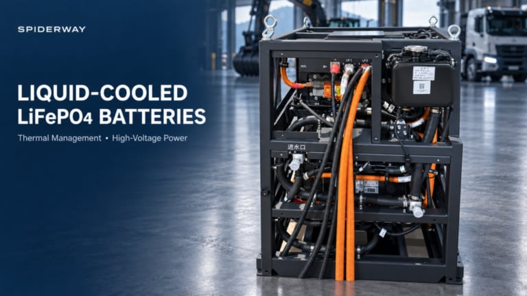
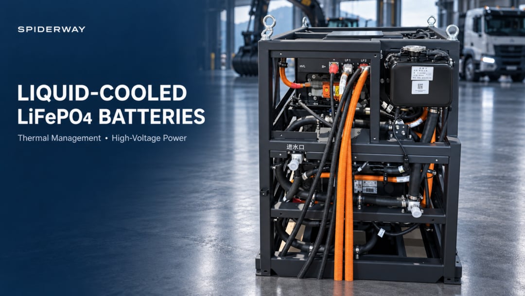
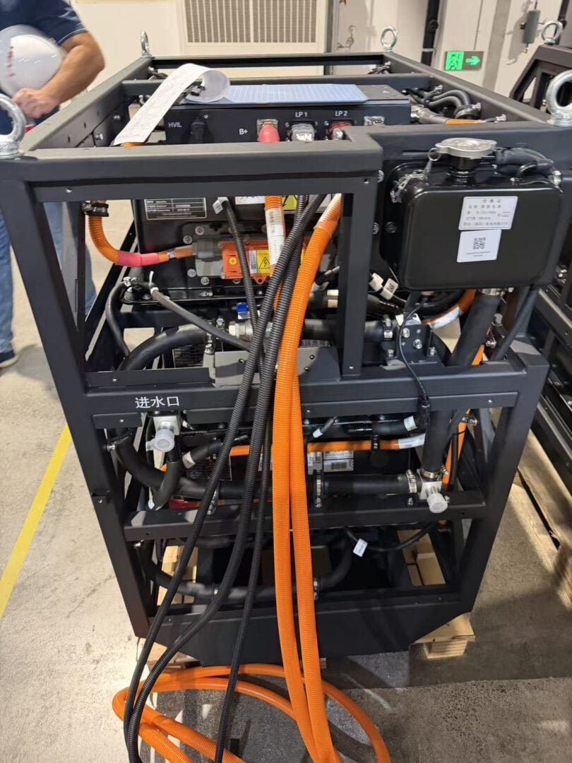
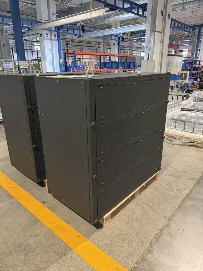
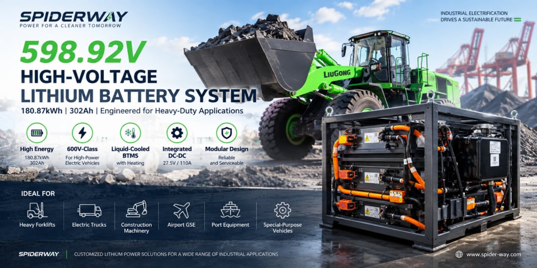
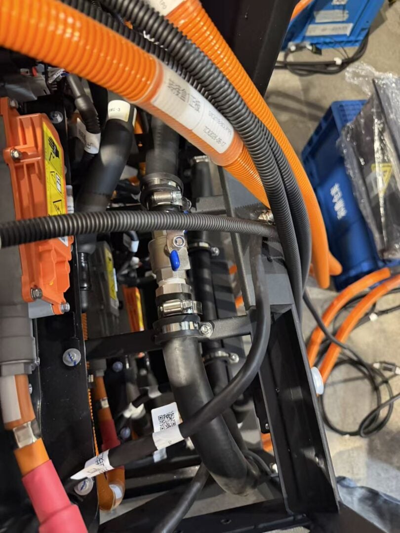
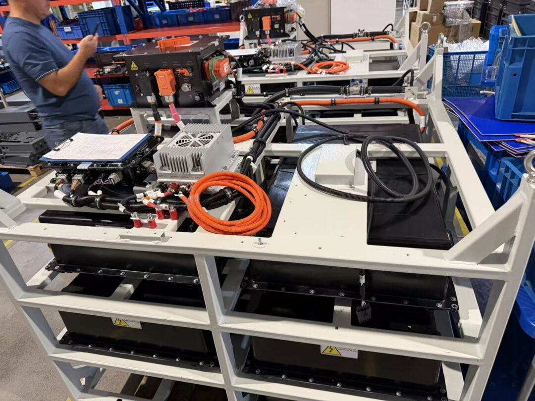
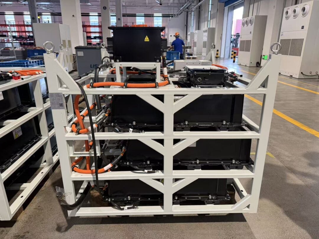
The supplied photographs show a framed equipment assembly with orange-sheathed electrical cables, liquid hoses, clamped connections, a capped reservoir-like component and an inlet marking. A close-up shows a valve and pipe connection near electrical equipment.
These visible features illustrate the physical integration challenges of liquid-cooled power systems: routing, connector access, hose support, vibration exposure and service clearance. They do not establish cell chemistry, voltage, capacity, cooling capacity, ingress protection or certification. Those characteristics require the relevant bill of materials, drawings, datasheets and test records. Identifying the assembly’s exact internal cooling architecture from exterior photographs alone would be unreliable.
Factory Acceptance: How to Verify a Liquid-Cooled Traction Battery
A procurement specification should connect each performance claim to a measurable acceptance condition.
| Validation item | What to define and record |
|---|---|
| Continuous-power capability | Starting state of charge, ambient temperature, coolant conditions, load duration and any derating |
| Repeated-duty performance | Representative work cycle, rest periods, duration and temperature accumulation |
| Thermal uniformity | Highest and lowest measured cell temperatures, sensor locations and load history |
| Charging performance | Starting temperature, state-of-charge interval, charger rating and actual power curve |
| Hydraulic integrity | Specified leak-test method, pressure conditions, allowable leakage and flow/pressure relationship |
| Electrical protection | Insulation verification and functional checks of relevant protection circuits |
| Fault handling | Verified response to cooling, sensor and communication failures |
| Environmental durability | Application-specific vibration, thermal cycling, moisture and contamination requirements |
| Auxiliary consumption | Pump, fan, compressor and heater energy over the representative duty cycle |
| Production traceability | Pack identity, critical component records, software version and acceptance results |
A short factory power test cannot establish long-term cycle life. Likewise, a cell-level test or certificate does not automatically apply to every pack configuration or vehicle installation. Agree the applicable validation scope for the exact product and destination market.
SPIDERWAY’s Manufacturing Foundation for Industrial Battery Projects
SPIDERWAY is based in Hefei, Anhui, and provides industrial LiFePO4 battery solutions with OEM/ODM customization. Our published company information describes applications including forklifts, loaders, excavators, aerial work platforms and airport ground support equipment. It also identifies sourcing from established cell suppliers, including CATL and BYD; the cell model for any project should be confirmed in its approved specification.
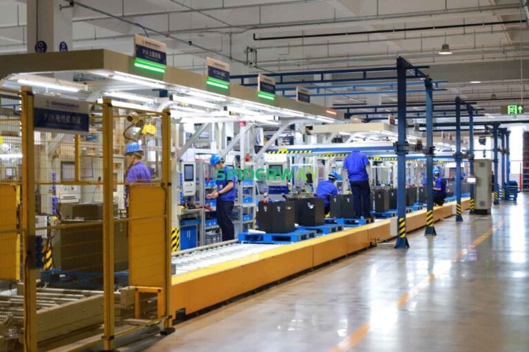
Our published factory overview describes automated assembly, battery testing and quality inspection. These capabilities provide a manufacturing foundation for repeatable industrial battery production.
For buyers, the practical advantage of working directly with an industrial battery manufacturer is the opportunity to resolve cell selection, mechanical packaging, electrical interfaces and production requirements within one project discussion.
For a custom liquid-cooled LFP battery program, our recommendation is to establish a project-specific engineering package covering:
- The complete voltage window, usable energy and continuous/peak power requirements.
- Vehicle installation dimensions, mounting loads and connector access.
- Cell operating limits and BMS charge/discharge permissions.
- Coolant inlet conditions, flow requirements and heat-rejection responsibility.
- Charger and vehicle communication requirements.
- Acceptance testing, service documentation and model-specific warranty terms.
This makes factory capability relevant to the customer’s actual machine. The exact high-voltage liquid-cooled configuration, available options and performance commitments should be agreed through the project specification.
When Is Liquid Cooling Worth the Added Complexity?
The strongest case usually involves sustained high load, repeated charging, high ambient temperature or packaging that limits direct cell airflow.
Construction machinery can combine repeated hydraulic power demand with dust, vibration and low vehicle speed. Heavy-duty transport can combine prolonged traction demand with rapid charging requirements. Some intensive industrial and airport operations also create repeated thermal loads with limited recovery time.
Evaluate the result over the whole duty cycle. Cooling consumes energy, and liquid circuits add maintenance tasks. Their value may come from more stable work output and less temperature-related downtime rather than lower auxiliary consumption.
A useful comparison is the energy and operating cost per completed task, with the same payload, route, ambient conditions and charging schedule. This avoids rewarding a low-power cooling system that saves auxiliary energy only by allowing the machine to derate.
Frequently Asked Questions
Does Every LiFePO4 Battery Need Liquid Cooling?
No. The appropriate thermal architecture depends on heat generation, climate, charging intensity, enclosure design and allowable temperature variation. Passive or air-cooled systems can be suitable for less demanding duty cycles.
Can a Liquid-Cooled LFP Battery Operate in Cold Weather?
Cooling alone does not provide cold-weather readiness. A system intended for cold operation may need a heater, freeze-protected coolant and temperature-dependent charging limits. Coolant freeze protection does not establish safe charging conditions inside the cells.
Does Liquid Cooling Make Charging Faster?
It can help when heat is limiting charge current. Actual charging speed remains constrained by the cell specification, initial conditions, BMS limits and charger capability.
Is a High-Voltage Liquid-Cooled Battery More Energy Efficient?
It can reduce certain power-distribution losses and maintain a more suitable thermal operating range. However, pumps, fans and refrigeration consume energy. Overall efficiency must be measured at a defined system boundary over a representative duty cycle.
What Temperature Difference Should an OEM Specify?
Specify maximum cell temperature, permissible cell-to-cell spread, and the load, ambient, coolant and measurement conditions under which they apply. A temperature-difference number without its test conditions is incomplete.
What Information Does SPIDERWAY Need for an Initial Project Review?
Provide the equipment application, voltage range, energy target, load profile, charging schedule, climate, installation space and vehicle communication requirements. Include the available thermal system or identify whether battery cooling equipment must be included in the project scope.
Engineering Conclusion
A liquid-cooled LiFePO4 battery pack delivers value when the cell interfaces, coolant circuit, heat-rejection hardware and control strategy are designed as one system. The potential benefits are more consistent continuous power, better temperature uniformity and more predictable charging under demanding conditions.
For a high-voltage liquid-cooled battery, those thermal benefits complement an electrical architecture designed for substantial power delivery. Neither higher voltage nor liquid cooling removes the need for application-specific validation.
Discuss your liquid-cooled traction battery requirements with SPIDERWAY. Share your machine’s duty cycle, electrical requirements and installation constraints so the proposed battery system can be evaluated against the work it must perform.
Supplier & Author Profile

- SpiderwayVerified
SPIDERWAY is a trusted LiFePO4 battery manufacturer specializing in golf cart, marine, RV, solar energy storage, industrial, and custom lithium battery solutions. We deliver OEM/ODM services, factory-direct quality, global shipping, and expert support for distributors, brands, and wholesale buyers worldwide.
Latest entries
- 2026-09-17Liquid-Cooled LiFePO4 Battery Packs for Heavy-Duty Electric Machinery
- 2026-09-16598.92V 180.87kWh High-Voltage Lithium Battery System for Heavy-Duty Electric Machinery
- 2026-09-08Exploring SPIDERWAY’s LiFePO4 Battery Plant in Hefei: A Look Inside an Advanced Industrial Lithium Battery Production Line
- 2026-09-08Evolution of LiFePO4 Battery Energy Density: A Decade of Advances and Future Outlook (2015–2035)