598.92V 180.87kWh High-Voltage Lithium Battery System for Heavy-Duty Electric Machinery
Engineering a 598.92V 180.87kWh High-Voltage Battery System for Heavy-Duty Electric Machinery
By the SPIDERWAY Product Engineering Team
Electrifying a heavy-duty forklift, wheel loader, construction machine, terminal tractor or other high-power industrial vehicle differs fundamentally from swapping in a conventional low-voltage traction battery. As equipment power rises, battery engineering extends beyond cells and capacity into a complete system: high-voltage distribution, battery management, thermal control, DC-DC conversion, mechanical integration and vehicle communication.
The high-voltage battery system reviewed by the SPIDERWAY Product Engineering Team is rated at 598.92V, 302Ah and 180.87kWh. Its modular architecture combines multiple battery packs, a structural mounting frame, liquid-based thermal management, high-voltage interconnections, system-level battery control and a VAPEL high-voltage-to-27.5V DC-DC converter.
This article examines the system from an engineering standpoint and explains why this kind of 600V-class high-voltage lithium battery system is increasingly relevant to heavy-duty electric vehicles and off-highway machinery.
1. System-Level Specifications
Based on the equipment labels and components examined by our engineering team, the principal system parameters are:
| Parameter | Specification |
|---|---|
| System Voltage | 598.92V |
| System Capacity | 302Ah |
| System Energy | 180.87kWh |
| Voltage Class | Approx. 600V |
| Thermal Architecture | Liquid thermal management / BTMS |
| Low-Voltage Conversion | Integrated high-voltage DC-DC |
| DC-DC Output | 27.5V, up to 110A |
| Mechanical Architecture | Modular stacked battery packs |
| System Controller Software Model | CEB-B70S |
| System Controller Hardware Model | CEB-B70H |
| Typical Target Equipment | Heavy industrial and off-highway electric vehicles |
The three principal electrical ratings are mathematically consistent:
598.92V × 302Ah = 180,867.84Wh ≈ 180.87kWh
This matters because industrial battery specifications should always be assessed as a complete electrical system rather than as isolated marketing figures.
An Important Note About CEB-B70S / CEB-B70H
The equipment label identifies:
Software Model: CEB-B70S
Hardware Model: CEB-B70H
These identifiers should not automatically be interpreted as battery-cell model numbers or cell capacities.
Without a cell-level specification sheet, pack BOM or manufacturer documentation identifying the exact cell, it would be technically inappropriate to infer a cell’s Ah rating, series/parallel configuration or chemistry solely from these controller model designations.
This distinction matters in professional battery engineering.
2. More Than a Battery Pack: A Complete High-Voltage Energy System
The equipment shown in the production photographs illustrates the difference between a conventional industrial battery and a modern high-voltage vehicle energy system.
At a simplified level, the architecture can be represented as:
Battery Cells / Modules
↓
Battery Packs
↓
High-Voltage Interconnection
↓
BMS / System Controller
↓
High-Voltage Distribution
↓
Vehicle Inverter & Traction System
At the same time, two supporting systems operate alongside the traction power path:
Battery Packs → Liquid BTMS → Temperature Control
and:
~600V HV Bus → DC-DC Converter → 27.5V Vehicle Low-Voltage Network
This system-level architecture is particularly important in heavy machinery, because the battery must interact continuously with propulsion, hydraulic systems, charging equipment, auxiliary loads and vehicle controllers.
3. Why Use a 600V-Class Battery Architecture?
Industrial vehicles have traditionally used relatively low battery voltages. Forklift batteries, for example, commonly operate at 24V, 36V, 48V or 80V depending on equipment size.
That approach becomes increasingly challenging as vehicle power rises.
Electrical power is fundamentally related to voltage and current:
P = V × I
For the same power demand, increasing system voltage reduces the current required.
Consider a simplified 200kW electrical load while ignoring conversion losses:
At 80V, theoretical current would be approximately 2,500A.
At approximately 600V, it would be about 333A.
Actual vehicle engineering is more complicated, but the principle explains why high-power electric trucks and construction machinery migrate toward higher-voltage architectures.
Lower current for a given power level can make it easier to manage conductor size, resistive losses, connectors and high-power electrical components.
This does not mean higher voltage is automatically superior. A 600V-class architecture introduces much stricter requirements for insulation, creepage and clearance, connectors, service procedures, HVIL, contactors, pre-charge circuits and personnel safety.
High voltage therefore represents a system engineering decision, not simply a performance specification.
4. 180.87kWh for Energy-Intensive Duty Cycles
The system provides approximately 180.87kWh of nominal energy.
For heavy equipment, however, kWh alone does not determine operating time.
Actual runtime depends on:
- average traction demand;
- hydraulic-system consumption;
- auxiliary loads;
- terrain and gradients;
- payload;
- acceleration frequency;
- operator behavior;
- ambient temperature;
- usable SOC window;
- regenerative-energy recovery;
- equipment idle time;
- battery and drivetrain efficiency.
This is why SPIDERWAY does not recommend specifying a heavy-duty battery solely by asking, “How many kWh does the machine need?”
A better engineering process begins with the duty cycle.
For example, a terminal tractor operating predictable routes inside a logistics facility can have a very different energy profile from a wheel loader repeatedly loading aggregate, even if their peak traction power is similar.
5. Modular Battery Packs and Stacked Mechanical Architecture
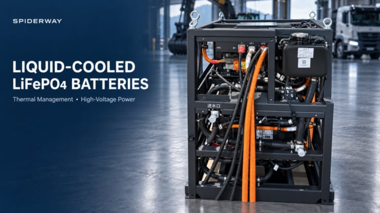
One of the most distinctive features visible in the production images is the use of multiple battery enclosures installed within a rigid structural frame.
This is particularly suitable for heavy equipment.
Passenger EVs can often distribute batteries across a wide, flat underfloor area. Construction machinery, large forklifts and specialized industrial vehicles frequently have very different packaging constraints.
Available battery space may be:
- behind the operator cab;
- within a former engine compartment;
- between structural members;
- inside a counterweight region;
- vertically arranged;
- divided between multiple vehicle locations.
A modular architecture gives vehicle engineers considerably more packaging flexibility.
Structural Frame
The heavy steel frame visible around the battery modules serves several functions.
It supports and locates the battery packs, provides mechanical mounting points, organizes electrical and thermal connections and allows the complete assembly to be handled as a vehicle subsystem.
Large lifting eyes are also visible on the assemblies.
For batteries of this scale, lifting provisions are an important practical consideration during:
manufacturing → transport → vehicle installation → inspection → service → replacement.
The frame must ultimately be engineered according to the target vehicle’s static and dynamic loads rather than treated as simple packaging.
6. Liquid Battery Thermal Management System (BTMS)
Thermal management becomes increasingly important as battery energy and power increase.
The photographs show extensive coolant plumbing and clearly identified coolant interfaces, including a marked inlet.
This indicates that the battery architecture incorporates a liquid-based Battery Thermal Management System (BTMS).
During high-power discharge and charging, battery cells and electrical components generate heat. If this heat is not adequately managed, temperature can become uneven across the battery system.
A liquid thermal circuit can transfer thermal energy between the battery packs and the system’s cooling/heating equipment.
Depending on the final vehicle configuration, the BTMS may support:
cooling during high-load operation and charging, as well as thermal conditioning or heating during low-temperature operation.
For heavy equipment, this capability is especially relevant to:
- continuous multi-shift operation;
- high ambient temperatures;
- high-power charging;
- repeated acceleration and lifting;
- construction environments;
- mining operations;
- cold-weather operation.
The objective is not simply to make the battery “cold.” Good thermal engineering aims to maintain the battery within its intended operating temperature window while controlling temperature differences across the system.
7. Integrated High-Voltage to 27.5V DC-DC Conversion
Another important component visible in the system is a VAPEL switching power supply / DC-DC converter.
The component label indicates an output of:
27.5V DC, up to 110A
This component addresses an important vehicle-engineering problem.
The traction battery operates around 600V, but many vehicle components operate on a much lower voltage electrical network.
The architecture therefore becomes:
598.92V High-Voltage Battery
↓
HV-to-LV DC-DC
↓
27.5V Low-Voltage Bus
↓
Vehicle Auxiliary Systems
Depending on the vehicle design, the low-voltage network can support controllers, instrumentation, relays, lighting, communication devices and other auxiliary equipment.
Integrating this conversion function within the overall battery/electrical solution can reduce the number of independent subsystems that the vehicle OEM must package and interface.
8. BMS and System Controller: The Intelligence Layer
The battery controller visible in the system is another critical element.
A modern high-voltage battery cannot operate safely by connecting several packs directly to an inverter.
The BMS and associated system controller coordinate battery operation and communicate with the vehicle.
Depending on the final configuration, functions can include:
- cell and pack voltage monitoring;
- temperature monitoring;
- SOC estimation;
- current monitoring;
- fault detection;
- charge/discharge protection;
- contactor control;
- pre-charge management;
- thermal-management coordination;
- insulation monitoring integration;
- CAN communication;
- diagnostic reporting.
For an OEM project, CAN communication is frequently one of the most important integration tasks.
The battery, vehicle control unit, inverter, charger, instrument cluster and thermal-management controller must exchange the correct messages at the correct time.
A mechanically compatible battery is therefore not necessarily an electrically or digitally compatible battery.
9. High-Voltage Cabling and Connectors
The orange cables visible throughout the system identify the high-voltage power circuits.
In equipment operating around 600V, cable and connector selection must consider considerably more than conductor current rating.
Engineering considerations include:
voltage rating, insulation, temperature, bend radius, vibration, connector locking, environmental sealing, abrasion protection, routing and service accessibility.
High-voltage cable routing should also be separated appropriately from sensitive communication and low-voltage signal circuits.
The dense but organized routing visible in these assemblies illustrates how much of high-voltage battery engineering takes place outside the cells themselves.
10. Application: Heavy-Duty Electric Forklifts
Heavy forklifts represent a natural extension of industrial electrification.
For relatively small forklifts, conventional low-voltage traction architectures remain highly effective.
However, as lifting capacity and vehicle power increase—particularly for equipment used in ports, steel mills, timber operations and heavy manufacturing—the engineering trade-offs change.
A 600V-class system can become relevant for large machines requiring substantial traction and hydraulic power.
Potential applications include:
heavy-capacity forklifts, container-handling equipment and specialized material-handling vehicles.
For diesel-to-electric conversion projects, battery integration must be coordinated with the motor, inverter, hydraulic system, vehicle controller, charging equipment and mechanical counterweight requirements.
11. Application: Electric Wheel Loaders and Construction Machinery
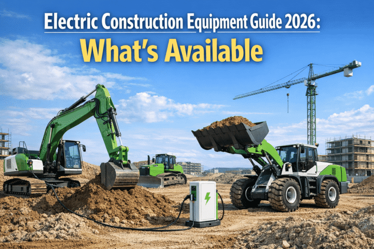
The modular high-voltage architecture is particularly relevant to electric construction machinery.
Potential equipment includes:
- wheel loaders;
- excavators;
- material handlers;
- mining equipment;
- drilling machinery;
- specialized off-highway vehicles.
These machines often experience high transient loads, vibration, dust and long operating periods.
They may also require significant electrical power for both traction and work functions.
For example, an electric loader needs energy not only to move the machine but also to operate the systems responsible for repeated loading cycles.
This makes battery power capability and thermal performance just as important as total energy capacity.
12. Application: Electric Trucks and Terminal Tractors
A modular 600V-class battery system can also be engineered for commercial vehicle applications.
Relevant platforms may include:
yard tractors, terminal tractors, short-distance logistics trucks, vocational vehicles and other heavy electric trucks.
A 180.87kWh system should not automatically be advertised with a fixed driving range.
Vehicle range depends heavily on gross vehicle weight, speed, road gradient, HVAC demand, auxiliary equipment and operating pattern.
For professional B2B specification, SPIDERWAY therefore prefers to calculate energy requirements from the customer’s actual operating profile.
13. Application: Airport GSE and Port Equipment
Airport and port environments are particularly suitable for industrial electrification because many vehicles operate within controlled geographic areas and return regularly to known charging locations.
Potential applications include:
aircraft tractors, high-power airport GSE, terminal tractors, port AGVs and specialized cargo-handling vehicles.
These applications can nevertheless impose demanding duty cycles.
Repeated acceleration, towing and high equipment utilization make thermal management, charging strategy and power capability critical design variables.
14. From Open Engineering Assembly to Enclosed Vehicle Battery
The photographs also show battery systems at different stages of integration.
Some assemblies expose the battery packs, high-voltage wiring and thermal connections inside the structural frame. Others are enclosed within large black housings.
This reflects a normal engineering progression:
Battery Pack
→ Module Integration
→ Structural Frame
→ Electrical & Thermal Integration
→ System Testing
→ Protective Enclosure
→ Vehicle Installation
The open-frame version provides excellent service and engineering access during manufacturing and integration.
The enclosed system provides additional mechanical and environmental protection for the finished vehicle application.
The final enclosure design must be determined by application requirements, including environmental exposure and applicable protection standards.
15. Engineering a Battery for the Machine — Not the Other Way Around
At SPIDERWAY, our engineering approach begins with the vehicle.
Before specifying a high-voltage industrial battery system, the following information should be established:
| Vehicle Data | Why It Matters |
|---|---|
| Equipment type/model | Defines overall architecture |
| Rated & peak motor power | Determines power requirements |
| Inverter voltage window | Determines battery voltage compatibility |
| Average operating power | Helps calculate required energy |
| Duty cycle | Determines realistic runtime |
| Installation envelope | Determines battery packaging |
| Maximum battery mass | Affects structural integration |
| CAN protocol | Determines electronic compatibility |
| Charging strategy | Determines charger and thermal requirements |
| Ambient temperature | Influences BTMS design |
| Operating environment | Influences enclosure/protection requirements |
| Required operating hours | Determines usable battery capacity |
Only after these parameters are understood should voltage, capacity, cooling architecture and battery packaging be finalized.
This is particularly important for OEM/ODM and diesel-to-electric conversion projects, where simply installing the largest possible battery rarely produces the best vehicle.
SPIDERWAY High-Voltage Lithium Battery Solutions for Heavy Equipment
SPIDERWAY develops and manufactures lithium battery solutions for industrial and commercial electric vehicles, with applications spanning material handling, airport ground support, industrial mobility and specialized equipment.
Our product engineering work covers battery systems for applications including forklifts, heavy-duty material-handling equipment, GSE, AGVs/AMRs, aerial work platforms, industrial cleaning equipment and other electric vehicles, while high-voltage platforms extend this engineering capability toward larger construction and commercial machinery.
For high-voltage OEM and ODM projects, the SPIDERWAY engineering team can work with equipment manufacturers and system integrators on:
battery architecture → mechanical packaging → BMS integration → CAN communication → high-voltage interfaces → thermal management → charging integration → vehicle-level matching.
The 598.92V / 302Ah / 180.87kWh system examined here demonstrates an important direction in industrial electrification: the battery is no longer an isolated component.
It is becoming an integrated energy, thermal, electrical and digital subsystem of the machine.
For heavy-duty equipment manufacturers, that distinction is fundamental.
Talk to the SPIDERWAY Engineering Team
If you are developing an electric forklift, wheel loader, construction machine, electric truck, airport GSE, port vehicle or other high-power industrial EV, provide SPIDERWAY with your vehicle specifications, inverter voltage range, motor power, operating cycle, installation dimensions and charging requirements.
Our engineering team can evaluate the appropriate high-voltage lithium battery architecture for your equipment and develop an OEM/ODM integration solution around the actual machine.
Supplier & Author Profile

- SpiderwayVerified
SPIDERWAY is a trusted LiFePO4 battery manufacturer specializing in golf cart, marine, RV, solar energy storage, industrial, and custom lithium battery solutions. We deliver OEM/ODM services, factory-direct quality, global shipping, and expert support for distributors, brands, and wholesale buyers worldwide.
Latest entries
- 2026-09-17Liquid-Cooled LiFePO4 Battery Packs for Heavy-Duty Electric Machinery
- 2026-09-16598.92V 180.87kWh High-Voltage Lithium Battery System for Heavy-Duty Electric Machinery
- 2026-09-08Exploring SPIDERWAY’s LiFePO4 Battery Plant in Hefei: A Look Inside an Advanced Industrial Lithium Battery Production Line
- 2026-09-08Evolution of LiFePO4 Battery Energy Density: A Decade of Advances and Future Outlook (2015–2035)